MPR (Multi-Planar Reconstruction)
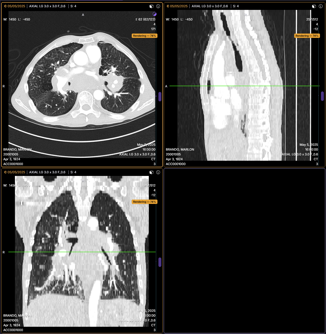
Multi-Planar Reconstruction (MPR) generates orthogonal and oblique anatomical views from a volumetric image series.
MPR displays:
- Axial
- Sagittal
- Coronal
- Oblique (arbitrary angle, defined via crosshair rotation)
These views may be arranged in either:
- Horizontal (3x1) layout
- Vertical (1x3) layout
Overview
Each viewport represents a different anatomical plane.
- Navigation and interaction are synchronized across all three planes
- User actions in one viewport update the corresponding location in the others
Volume Rendering Feedback
MPR viewports display an in-viewport Rendering Progress (%) indicator during volume loading, so users know exactly when high-resolution volume data is fully loaded.
Image processing controls — such as Maximum Intensity Projection and slab thickness adjustment — are held until volume data is completely loaded, ensuring these functions only operate on fully loaded, accurate volume data.
Navigation
Slice-Based Navigation
Slice-based navigation is used when the dataset is properly aligned.
- Navigation occurs slice-by-slice based on acquisition
- Mouse wheel scroll advances slices
- Click and drag advances by slice thickness
- The overlay displays slice numbers
Volume-Based Navigation
Volume-based navigation is used when slice alignment is not suitable, such as:
- Gantry tilt relative to the patient
- Patient rotation relative to the table
In this mode:
- Navigation occurs through reconstructed volume data
- The overlay displays "NA" instead of slice numbers
Crosshair Interaction
The Crosshair Tool enables synchronized navigation across all MPR viewports.
- The crosshair identifies the same anatomical point across all planes
- Moving the crosshair updates all corresponding views
- Crosshair rotation adjusts the orientation of the planes
Oblique Reconstruction
Oblique reconstruction allows the MPR cutting plane to be rotated to any arbitrary angle through the volume, going beyond the standard axial, sagittal, and coronal orientations. This is achieved by rotating the crosshair in any MPR viewport, which redefines the reference plane at the desired angle.
This capability is particularly useful when anatomy does not align with standard orthogonal planes — for example, following the true axis of a vessel, the angle of a vertebral endplate, or cardiac short-axis and long-axis orientations.
Oblique reconstruction is driven by crosshair rotation. Rotating the crosshair in any MPR viewport redefines the corresponding reference plane at the selected angle, and all synchronized viewports update accordingly.
At this time, curved (curvilinear) reconstruction is not supported. Oblique reconstruction is limited to flat planes at arbitrary angles through the volume.
Using Oblique Reconstruction
- Open a study containing a supported volumetric image series and enter MPR mode
- Activate the Crosshair Tool
- In any MPR viewport, rotate the crosshair to define the desired oblique angle
- The corresponding reference plane updates in real time, and synchronized viewports reflect the new orientation
- Use slab thickness adjustment in combination with oblique planes to control the depth of data included in the reconstructed view
Double Oblique
A double oblique plane can be defined by rotating the crosshair on two axes simultaneously across two different MPR viewports. All synchronized viewports will update to reflect the compound plane orientation.
Use oblique reconstruction when anatomy is not aligned with standard planes — for example, when assessing cardiac structures, angled spinal levels, or vessels that run obliquely through the volume.
When using oblique planes in multi-series MPR, crosshair rotation applies to the most recently activated viewport. Confirm the correct viewport is active before rotating to avoid unintended plane changes in other series.
Slab Thickness
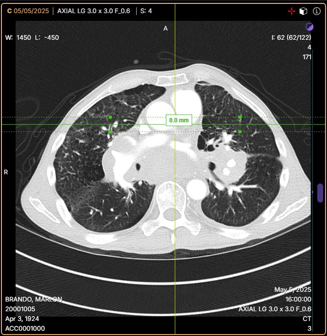
Slab thickness controls the depth of image data included in the reconstructed view. Slab thickness can be applied to oblique planes in the same way as standard orthogonal planes.
Adjustment
- Select and hold a crosshair anchor point
- Drag to increase or decrease slab thickness
- The thickness value is displayed dynamically during adjustment
SnapTo
Slab thickness adjustment supports a SnapTo function:
- With Shift held: Slab thickness snaps to 0.5 mm increments
- Without Shift: Slab thickness can be manually adjusted to 0.1 mm increments
Behavior
- The value disappears when the interaction ends
- Hovering over the anchor point displays the current thickness
- When applied across multiple axes, values are displayed for each axis
Projection Functions
When slab thickness is greater than a single slice, the Projection Functions control determines how the voxel values across the slab depth are combined into a single displayed image.
Projection Functions are accessed via the viewport options menu:
- Open the viewport options menu (top-right corner of the active viewport)
- Select Projection Functions
- Choose the desired projection mode from the submenu
Available Modes
| Mode | Description | Best Used For |
|---|---|---|
| Composite | Blends voxel values across the slab using a composite rendering algorithm | General anatomical review; balanced representation of structures within the slab |
| Maximum | Displays the highest voxel value along each ray through the slab (MIP) | Bright structures — contrast-enhanced vessels, bones, calcifications |
| Minimum | Displays the lowest voxel value along each ray through the slab (minIP) | Dark structures — airways, lung parenchyma, bowel gas |
| Average | Displays the mean voxel value along each ray through the slab (Mean IP) | Smoothing noisy data, liver parenchyma assessment, reducing streak artifacts |
The currently active projection mode is indicated by the label Active displayed next to the selected option in the submenu.
Projection Functions are only meaningful when slab thickness is greater than one slice. When viewing a single thin slice, the selected projection mode has no effect on the displayed image.
Use Maximum (MIP) to highlight vascular structures or calcifications. Use Minimum (minIP) to assess airways or lung parenchyma. Use Average for a balanced view of soft tissue density across the slab.
Multi-Series MPR
By default, MPR operates on a single image series.
Multi-series MPR allows simultaneous review of multiple datasets.
Setup
-
Configure a multi-viewport layout:
- 2x3 (two series)
- 3x3 (three series)
-
Load each series into corresponding planes:
- Axial
- Sagittal
- Coronal
-
Enable crosshair interaction across all viewports
Multi-Series Behavior
In multi-series MPR, interactions apply to the most recently activated viewport.
Crosshair interaction remains synchronized across all loaded series.
Slab thickness adjustments are applied only to the active viewport and may differ between series.
Behavior Notes
MPR functionality is available only for image series that support volumetric reconstruction.
Navigation behavior (slice-based vs volume-based) depends on image acquisition characteristics.
Use crosshair interaction together with MPR to accurately correlate anatomical locations across planes, including when working with oblique orientations.
Layout Behavior
These layout behavior scenarios apply exclusively when the system operates under its default configuration — no modality-specific layouts defined and the default 2x2 layout active.
When the default layout is applied, the system's layout restoration logic behaves as expected when transitioning from MPR mode back to common layouts. However, behavior can diverge based on the starting configuration and interaction path.
Scenario 1: 1x1 Layout Restoration After MPR
Starting from a common 2x2 layout, the user places a new series in viewport A, then enters MPR mode through viewport B. Upon navigating to a common 1x1 layout, the system will:
- Restore the content previously shown in viewport A, preserving the user's selection before MPR was initiated.
- Ignore any series loaded during the MPR session, ensuring consistency upon returning to the 1x1 layout.
This behavior ensures retention of viewport A's original content, whether it was system-assigned or manually selected.
Scenario 2: 2x2 Layout Shift After MPR
Starting from a common 2x2 layout, the user places a new series in viewport A, then enters MPR mode via viewport B. Upon returning to the 2x2 layout, the system will:
- Retain the newly placed series in viewport A.
- Restore the existing layout content, with all viewports shifted downward by one slot.
This shift is expected behavior. When a new series is added to viewport A before entering MPR, returning to a stack layout larger than the default 2x2 retains the previously applied series layout configuration, but any newly added viewports remain empty until manually populated. No reordering of viewport positions occurs across layouts.